RESISTANCE TEMPERATURE DETECTOR – The incorporates pure metals or certain
alloys that increase in resistance as temperature increases and conversely. Rtd
is basically a temperature transducer which converts the temperature into
resistance the output of the rtd is ohm.
rtd
has linear resistance temperature characteristics they have positive
temperature coefficient
types of rtd- generally here some types of rtd is given –
(1)
PT100
(2)
PT150
(3)
PT200
In our plant we are using only PT100
, PT100 means it shows the 100Ω resistance at zero degree
Celsius
Temperature
in °C |
||||||
−50
|
80.31
|
|||||
−45
|
82.29
|
|||||
−40
|
84.27
|
|||||
−35
|
86.25
|
|||||
−30
|
88.22
|
|||||
−25
|
90.19
|
|||||
−20
|
92.16
|
|||||
−15
|
94.12
|
|||||
−5
|
98.04
|
|||||
0
|
100.00
|
|||||
5
|
101.95
|
|||||
10
|
103.90
|
|||||
15
|
105.85
|
|||||
20
|
107.79
|
|||||
25
|
109.73
|
|||||
30
|
111.67
|
|||||
35
|
113.61
|
|||||
40
|
115.54
|
|||||
45
|
117.47
|
|||||
50
|
119.40
|
|||||
55
|
121.32
|
|||||
60
|
123.24
|
|||||
65
|
125.16
|
|||||
70
|
127.07
|
|||||
75
|
128.98
|
|||||
80
|
130.89
|
|||||
85
|
132.80
|
|||||
90
|
134.70
|
|||||
95
|
136.60
|
|||||
100
|
138.50
|
|||||
105
|
140.39
|
|||||
110
|
142.29
|
|||||
150
|
157.31
|
|||||
200
|
175.84
|
We should not use rtd at above 850⁰c above
850⁰c the linearity of rtd will ended and reading will be inaccurate. In our we
are using rtd at 550⁰c range only
Wiring configurations
Two-wire configuration

The simplest resistance thermometer configuration uses
two wires. It is only used when high accuracy is not required, as the
resistance of the connecting wires is added to that of the sensor, leading to
errors of measurement.
Three-wire configuration


In order to minimize the effects of the lead
resistances, a three-wire configuration can be used. Using this method the two
leads to the sensor are on adjoining arms. There is a lead resistance in each
arm of the bridge so that the resistance is cancelled out, so long as the two
lead resistances are accurately the same.
Four-wire configuration


The four-wire resistance thermometer configuration
increases the accuracy and reliability of the resistance being measured: the
resistance error due to lead wire resistance is zero. In the diagram above a
standard two-terminal RTD is used with another pair of wires to form an
additional loop that cancels out the lead resistance.


Range setting of rtd – to calibrate a rtd the
standard method is that take an ice bath reference for 0⁰c and arrange a
furnace for required higher according to use actually it is impracticable so we
purchase only calibrated rtd and set the range according to requirement we can
set the range of rtd by decade resistance box

Actually it is the calibration of indicator in
terms of temperature whatever temperature is sensed it is determined by rtd in
terms of resistance only because the output of the rtd is ohm but we see direct
temperature reading through indicator
First disconnect the rtd to the transmitter
then give 100Ω through DRB to the transmitter this time the scanner should show
zero if this value does not come press the zero button showing (here two button
first zero and another span )after that give resistance according to maximum
process temperature you want like you to 200 degree C give 175.84Ω if the
scanner does not show 200 then press span button and adjust
Pneumatic actuator
A Pneumatic actuator mainly consists
of a piston, a cylinder, and valves or ports. The piston is covered by a diaphragm, or seal,
which keeps the air in the upper portion of the cylinder, allowing air pressure
to force the diaphragm downward, moving the piston underneath, which in turn
moves the valve stem, which is linked to the internal parts of the actuator
Pneumatic cylinders (sometimes known as air cylinders) are mechanical devices which use the power of compressed gas
to produce a force in a reciprocating linear motion.
Like hydraulic
cylinders, something forces a piston to move in the desired direction. The
piston is a disc or cylinder, and the piston rod transfers the force it
develops to the object to be moved. Engineers prefer to use pneumatics sometime
because they are quieter, cleaner, and do not require large amounts of space
for fluid storage.
Because the operating fluid is a gas, leakage from a
pneumatic cylinder will not drip out and contaminate the surroundings, making
pneumatics more desirable where cleanliness is a requirement.
Pneumatic
actuator is basically a 5/2 solenoid valve where has 5 port two for outlet two
for exhaust and one for air inlet if one
coil uses we can operate the piston either fully open or fully closed condition
. if we want to stop the
piston at a certain desire position like 30% or 40% we have to use double
solenoid .
In our jamul plant ther are many
places where pnumatic actuator are going to use like in packers in cement silo to air slide here electric
motor damper actuator and pnumatic actuator both are present but in case if electric
motor doesn’t work we can operate the pnumatic actuator
Electric motor hydraulic
actuator –
in electric motor hydraulic actuator there is a motor which circulates the the
oil its function is similar like pneumatic actuator only difference hrere in
place of air oil is used

Figure - electric motor hydraulic actuator
Electric motor control damper
actuator – it
has 3 phase induction motor its operate the lever this actuator has primary and
secondary gear secondary gear also known as worm gear at front side there is
indicator which shows the position of damper at the back side wheel and handle
is given if we want to operate the actuator manually then push the handle
clockwise this thing bypasses the motor now we can easily set the position of
damper as per requirement through the wheel in this actuator there is an
advantage that we can adjust the damper at 30% , 40% etc but in

Electric motor damper actuator has 6 limit
switch as described further
2 limit switch for full open (1 for retendency
in case failure)
2 limit switch for full close condition (1 for
retendency in case failure)
1 for open torque (when we open the damper for
flow if there is obstruction like material jamming or some material struck
around)
1 for close torque (when we close the damper if there is obstruction like
material jamming or some material struck around foreign material coming )
Thermocouple- A thermocouple is a type of temperature
sensor, which is made by joining two
Dissimilar metals at one end. The joined end
is referred to as the HOT JUNCTION.
The other end of these dissimilar metals is
referred to as the COLD END or COLD
JUNCTION. The cold junction is actually formed
at the last point of thermocouple
Material certain combinations of metals must
be used to make up the thermocouple pairs.
If
there is a difference in temperature between the hot junction and cold
junction, a
Small voltage is created. This voltage is
referred to as an EMF (electro-motive force)
And can be measured and in turn used to
indicate temperature.
The
voltage created by a thermocouple is extremely small and is measured in terms
of
Millivolts (one millivolt is equal to one
thousandth of a volt). In fact, the human body
Creates a larger millivolt signal than a
thermocouple. The output of thermocouple is mV
Polarity checking of thermocouple take a multimeter it has two lead red and
black and our thermocouple has also 2 lead connect one lead of thermocouple to
multimeter red lead and another to another one if the multimeter shows +ve
reading the terminal connected to red is positive terminal of thermocouple and
if shows –ve the terminal connected to red is negative terminal of thermocouple


Thermocouple connection to
hart calibrater
COLD JUNCTION COMPENSATION -
the last point of thermocouple material is
known as the cold
junction. The amount of output the t/c
produces is determined by the difference
between the hot junction and the cold junction
temperatures. The cold junction
temperature must be known to accurately
determine the temperature.
Lets
look at the following examples;
If we
had a thermocouple in a heat treat furnace and wanted to know what
temperature it was in that furnace, we could
attach a voltmeter to the cold junction
and measure the voltage.
Let’s
say that the furnace is operating at 1000 deg.C. and it is 100 deg. C at the
cool end of the T/C. Since we said that a T/C
measures the difference between the
hot and cold junctions, our formula would be:
1000
(hot junction) - 100 (cold junction) = 900 deg. C.
There
seems to be a problem since we said that the furnace was at 1000 deg. F.
This brings us to COLD JUNCTION COMPENSATION.
COLD
JUNCTION COMPENSATION is usually done automatically by the measuring
instrument. The instrument measures the
temperature at the cold junction and adds it
back to the equation.
1000
(hot junction) - 100 (cold junction) = 900 deg. C + 100 deg. C
(cold
junction temp) = 1000 deg C
This
way the instrument indicates the actual temperature of the hot junction.
This COLD JUNCTION compensator is usually
located at the terminals on the back
of the indicating instrument and you must
maintain T/C material all the way to this
point.
In our plant we use hart for this, connection
with hart to t/c is shown in figure hart
is also uses for range setting
For compensation we give any certain voltage through
the multimeter to t/c voltage depends on the atmospheric temperature consider 1.5mV . we use 4-20mA system if the
multimeter shows some rating above than 4mA now then reverse the lead multimeter will show some reading less than
4mA here set the point with 0 deg C
Actually
every thermocouple designed for reference at 0 deg C but our atmosphere is at
30deg C thats why we needed cold
junction compensation
For a
thermocouple to function properly, there must be no other metals used between
the hot junction and the cold junction. If
wire is needed to connect the T/C to the
indicating instrument, the lead wire must be
made of the same material as the T/C.
Thermocouple types-
Type E: The Type E thermocouple has a Chromel
(Nickel-10% Chromium)
positive leg and a Constantan (Nickel- 45%
Copper) negative leg. Type E has a
temperature range of -330 to 1600F, has the
highest EMF Vs temperature values of
all the commonly used thermocouples, and can
be used at sub-zero temperatures.
Type E thermocouples can be used in oxidizing
or inert atmospheres, and should not
be used in sulfurous atmospheres, in a vacuum
or in low oxygen environments where
selective oxidation will occur. The color code
for TYPE E wire is purple and red.
Type J:
The Type J thermocouple has an Iron positive leg and a Constantan
negative leg. Type J thermocouples can be used
in vacuum, oxidizing, reducing and
inert atmospheres. Due to the oxidation
(rusting) problems associated with the iron
leg, care must be used when using this
thermocouple type in oxidizing environments
above 1000F. The temperature range for Type J
is 32 to 1400F and it has a wire
color code of white and red. THERMOCOUPLE
THEORY
Type K:
The Type K thermocouple has a Chromel positive leg and an Alumel
(Nickel- 5% Aluminum and Silicon) negative
leg. Type K is recommended for use
in oxidizing and completely inert
environments. Because it’s oxidation resistance is
better than Types E, J, and T they find widest
use at temperatures above 1000F.
Type K, like Type E should not be used in
sulfurous atmospheres, in a vacuum or in
low oxygen environments where selective
oxidation will occur. The temperature
range for Type K is -330 to 2300F and it’s
wire color code is yellow and red.
Type N: The Type N thermocouple has a Nicrosil
(Nickel-14% Chromium- 1.5%
Silicon) positive leg and a Nisil (Nickel-
4.5% Silicon- .1% Magnesium) negative
leg. Type N is very similar to TYPE K but is
less susceptible to selective oxidation
effects. Type N should not be used in a vacuum
or in reducing atmospheres in an
unsheathed condition. The temperature range is
32-2300 deg F and its wire color code
is orange and red.
Type T:
The Type T thermocouple has a Copper positive leg and a Constantan
negative leg. Type T thermocouples can be used
in oxidizing, reducing or inert
atmospheres, except the copper leg restricts
their use in air or oxidizing environments
to 700F or below. The temperature range for
Type T is -330 to 700F and it’s wire
color code is blue and red.
Optocoupler:
Optocoupler is a one type of
device which is used to work as a isolator between two frequency.
We are using in cement plant
different type of electronic circuit. In that electronic ckt.we are using in
different type of micro-processor.in that micro processer for doing work
require a oscillator ckt. in that oscillator we are giving ac power supply then
oscillator ckt generate frequency in mega-hz.so different type of company make
a different type of oscillator whose generate different frequency.
Construction of opto coupler:-1.LED
2. PHOTO TRANSMITTER

When we provide power supply to
the LED, it emits the light .this light is provide on the base of photo
transmitter. Then photo transmitter generates current this current is directly
proportional to the light.LED and photo transmitter are not electrically
connected. Only connected each other by the light. That device frequency not
interrupted each other because there is not induction effect.

From example we can see
optocoupler is a one type of isolator between two frequency . and from this
example we can understand that different type of instrument connected of each
other which is given same output (4-20mA)but its frequency is different like
2Khz,3kHz etc..But that frequency not interrupted each other .because there is
installed optocoupler . if we will not installed optocoupler then each frequency interrupt each other and this
disturbance is called “radio frequency disturbance” . For that disturbance
removed we use optocoupler
Optocoupler is a device and
isolator is a system. In weigh feeder and VFD very necessary to use isolator.
From one isolator we can take
1,2,3 etc. Output.
Magnetic separator:-type
of magnetic separator
1. permanent magnet
2. electromagnet
3. magnetic separator
1. Permanent magnet:-by manual cleaning

We know this is a permanent.
Which is suspense above the belt conveyor. When any ferrous material come with
the lime stone, then it is attracted by the permanent magnet .after some it
clean by manually or as per schedule.
In Jamul plant this device is installed crusher` s no 1 above the
belt conveyor.
2. Electromagnet: - it can be both type manually
or automatic

In this magnetic separator a
temporary magnet happens. This is suspended above the belt conveyor. In this
magnetic separator have a coil. When we provide electric supply in this
separator then emf induced in this coil. This supply can happen 110V AC or dc,
24 V DC OR 230V AC etc. when ferrous material come with the lime stone then
electro magnet attract this material. It material clean by manually or
automatic as par schedule. For automatic, this electromagnet`s interlocking
with the belt conveyor when conveyor`s supply off then material fall down on the belt then clean the belt.
This device is installed in Jamul plant crusher no 2 above the
belt conveyor
3. Magnetic separator:- in this system one electromagnet
suspense above the belt conveyor. In this electromagnet around a small belt
installed with the help of idler. This belt is rotate around the electromagnet.
For giving belt rotation one motor is installed. This motor gives supply
separately. When we provide supply on the electromagnet then emf is generate on
his coil. When ferrous material come with the material (i.e. coal, limestone
etc.).Then it is attract by the electromagnet. Rotating belt this material
separate out of the belt . So material is separate from the main material
This separation is two types
1.
Inline magnetic separator
2.
Cross belt magnetic separator

1.
Cross belt magnetic
separator:-this type of separator installed above the belt conveyor on The cross
condition.
2. Inline magnetic separator:-this
type of magnetic separator is installed above belt conveyor in the condition of
inline.
Metal detector:- for the detect metal from the material.

Generally this is installed above
the belt conveyor. These devices have a wooden frame which has up side and down
side one- one coil. Upper coil called transmitting coil and dipper coil called
receiving coil. One control box installed in these devices which have two PCB
(printed ckt board & Amplifier. One
PCB (printed ckt board) &Amplifier for transmitting coil. And One PCB
(printed ckt board) for receiving coil. Control box connect with the panel box
by the four core cable. Four core cable describe
1. Red for +12 volt
2. Black for -12 volt
3. blue- 0(zero)
4. yellow- for signal
In the penal box different type
of device like power supply card, logic card, sensitivity probe, transformer
etc. On the panel box door have 3 probes-
1.
for on/off
2.
for reset
3.
for acknowledgment

Working:-when we provide 24 volt dc on the
power supply card then supply goes to the PCB amplifier ckt. After that PCB
have a oscillator ckt. That oscillator generates 18-25 KHz frequency for
transmitting coil & same like this 16-18 KHz frequency for receiving coil.
So between transmitting coil & receiving coil something become a balance
magnetic field. In that time if we check voltage between zeros and signal then
we will find something -0.5 to -1 volt. Now if metal come with the limestone
(material) which will be disturbed of magnetic field then emf will be generate
around the metal which will take power from the supply. Then current will
disturb after that this current goes to the amplifier and amplifier, amplified
this current and signal send to the comparator which have on the logic card.
Then comparator will comparison between signals and o/p send the signal to
traic. After that traic operate relay
then belt will stop. After that attainder
will come and he push the
acknowledgement button then metal detector sense the signal after that
attainder clean the metal then he push reset button then metal detector again
start.
Remember always that metal`s come
in running condition then metal detector work if metal come and stop below
metal detector then metal detector will not work.
In Jamul metal detector installed both on the crusher`s belt
conveyor etc.
This is detecting 10 mm size and
more than 10mm.on the sensitivity probe 6 no cut by the potentiometer. If we
set sensitivity 1 then metal detector`s ability poor if we set sensitivity 6 than metal detector`s ability very high
&fast.
ADMITTANCE LEVEL LIMIT SWITCH
Ø When
material level in silo goes beyond a preset limit this switch will activated
and close the filling of silo
Ø When
material levels will high sensitivity indicator will reach high position and so
a GREEN LED will lights and after a
time delay RED LED will lights (COVERED TIME DELAY).
Ø When
material level will low sensitivity indicator will reach low position and after
a time delay (UNCOVERED TIME DELAY) RED LED will turn off.
Ø FAIL SAFE MODE:
If it is high(HI) then operator will acknowledge whether material level goes
high or power cut and vice versa.
Controller of
admittance level limit switch as shown in below:
GREEN
Sensor part of admittance limit switch

CO MONITERING SYSTEM
There are
two analyzer. Samples are coming form 3 points for each analyzer.
There are 3 points A, B & C in CO
gas analyzer. At a time one is working and one is cleaning [To remove dust
which accumulated during sampling] by air purge and another is in rest condition.
The sequence of A, B & C selected by
a logo PLC.
The sample gas comes to cooler
(Temperature should in between 1-4°c to maintain gas flow).From cooler it comes
to paper filter and through a pump it comes to GAS ANALYZER (Through a flow
meter).
If CO gas will high, then there will be
a risk of explosion because CO gas is self-burning.

DISTRIBUTED CONTROL SYSTEM(DCS) AND PROGRAMMABLE LOGIC CONTROLLER(PLC)
The
differences between DCS and PLC are: DCS (Distributed Control System) is a
CONTROL SYSTEM that works using several controllers and coordinates the work of
all these controllers. Each controller is handling a separate plant. This
controller is referred to the PLC.
PLC is an
automation tool. Automation developed to reduce human effort. In every industry
there is a process (Manufacturing chain).This manufacturing chain consists of a
list of activities. To do these activities we have to operate electrical and
other kinds of energy. We can operate this either by man power or by machine.
In ancient
days we have to monitor instruments on the location. Later we did it in one
room. But it creates a complicated hardware. And ultimately software has
developed and starts improving.PLC designed then and it completely consists of
logic.
To run a
process there is a system, sequence and this sequence consists of a list of
activities. We chart out these
activities in software and make logic (program, sequence). To run this logic
certain inputs are required. These inputs are coming from field and some inputs
we generate. According to this inputs logic runs and generate outputs. This
output finally goes to its destination. To catch inputs and fetch outputs to
its destination we require a number of input /output modules (they are
expandable but limited). [AI, AO, DI, DO]
By the
above arrangement (1) Hardware (2) Trouble-shooting become easy.
To interact with the running process runs by
PLC, we have to interface (communicate) with PLC. Human machine interface (HMI)
makes this opportunity.
PLC
capacities are two types. I/O capacity and MEMORY capacity. When this capacity
limits out, thinking has started to find new technology.
In
petrochemical and oil refinery industries number of AI,AO greater than DI,DO so
no of data processing greater than others which require large time, so speed of
processing slow(Analogue signal is time variant so no of bits are high BUT
Digital signals are 2-bit signals ) because burden on CPU increases. In that
situation conventional PLCs are unable to carry the process. Thus desired
output cannot get at desired time.
To overcome
this problem we use discrete (individual) controlling system. But we give a
common platform to this discrete controlling, and termed it as DCS. Thus burden
on CPU decreases.
In this
centralised system every controller connected in a common place, since they are
working individually they controlled by this common platform.
RETARDANCY: In critical places we use greater than one
similar unit.
e.g., we
use two power supplies just for back up. Here a battery is used to store edited
programs if both of power supply gets failed.
Two cables are used to connect CPU
with HMI.
RETARDANCY=
DEPENDANCY
In DCS system there are
Digital Inputs (switches, contacts {pressure switch, limit switch etc})
Digital Outputs (Solenoid valve coil supply {In Pneumatic Actuator}
etc) HI or LO
Analogue Inputs (Pressure Transmitter, Vibration Transmitter, Temperature Transmitter, VFD etc)
Analogue Outputs (Electro-hydraulic Actuator {force coil}, Weigh-Feeder TPH setting etc) 4-
20mA


CONTROLLER4=RAW MILL 1, 2&3CONTROLLER3= CEMENT MILL 4, 5&6 + CEMENT MILL7, 8 WEIGH-FEEDER (ON-OFF COMMAND)
M=CPU OF EACH
CONTROLLER (PROGRAMS ARE STORED IN THE MEMORY
OF THIS CPU AND THE INPUTS FROM FIELD COME HERE THROUGH DI&AI. ACCORDING TO PROGRAM
OUTPUT GENERATE AND GOES TO FIELD THROUGH AO&DO)
LIMIT
SWITCH
A limit switch is a switch operated by the motion
of a machine part or presence of an object. They are used for control of a
machine, as safety interlocks.
e.g., a person passing through the way beside the belt conveyor,
now if his shirt gets trapped in moving belt, then he
will pull a rope beside it termed as pull cord. This pull cord will move a
lever, and this lever will do a changeover contact thus an interlock will
operate to trip the belt.

PRESSURE
SWITCH
A pressure
switch is a form of switch that closes an electrical contact when a certain set pressure has been reached on its
input. The switch may be designed to make contact either on pressure rise or on
pressure fall.
In our plant
pressure switch is used to protect gear box. For lubrication in gear box the
oil pressure should be 1 kg/cm2.If it goes below 1kg/cm2 ,then
motor will trip by the changeover switch. To set this pressure a knob is
located at the upper side of the switch.

VIBRATING
FORK LEVEL LIMIT SWITCH
Tines
of vibrating fork in mechanical vibration of a resonance frequency of 80HZ by
piezoelectric materials. When service material covers the tines, they cause
damping of vibration .This stoppage of vibration sensed by electronic circuitry
& the signal after processing is used to operate a relay. Potential free
contacts of relay are available for alarm or control.
When tines
are free from material the fork starts vibration again and the relay contracts
revert to previous position.

DIFFERANTIAL PRESSURE TRANSMITTER:
WHAT IS DP TRANSMITTER?
This equipment will sense the
difference in pressure between two ports and produce an output signal with
reference to a calibrated pressure range.
CONSTRUCTION & WORKING OF DP
TRANSMITTER:
CONSTRUCTION:
The DP TRANSMITTER
has two parts. The upper part is transmitter and lower part is transducer.
|
|

Transducer:
- in this part it has two ports. One is high port and other one
is low port. In centre capsule is there, which contains carbon powder. It also
have diaphragm at both the sides of ports. These diaphragms are act as plates
of capacitor and the capsule (carbon powder) act as dielectric medium.
The
output of this transducer is CAPACITANCE.
This output gives to transmitter through a wire.
Transmitter:
- the transmitter is electronics based. It contains
microprocessor. It has 4 terminals, 2 for supply and 2 for output to DCS. It
also has security switch, fail safe mode, zero and span adjustment switch. The
output of transmitter is in MILLI AMPERE
(4 to 20m amps). It contains three
cards
Ø
Power card: -
Ø
CPU ( or memory card): -
Ø
Calibration card: -
WORKING: -
When high port is connected to at high pressure side
and low port is connected to low pressure side or kept open in atmospheric. The
diaphragms are act as plates of capacitor and the capsule (carbon powder) act
as dielectric medium. The both diaphragms are compresses the carbon powder
(dielectric medium). How much difference will takes place according to that the
output of the transducer e.i capacitance also changes. Our final output of the
transmitter (e.i 4 to 20m amps) also changes.
RANGE SETTING: -
We are setting the range of the transmitter by using
the zero adjustment switch and span adjustment switch.
ZERO ADJUSTMENT SWITCH: -
this switch is used to set the transmitter value at 0 pressures. To set this,
we are keeping the both port open, at this pressure the output is should be
4mA. If it is not 4mA then press the zero
adjustment switches for 5seconds.
SPAN
ADJUSTMENT SWITCH: - by using this switch we are setting
the value of the transmitter at MAX pressure. To set this value we giving the
max pressure at high port side and the output of transmitter should be show the
20mA. If not press the span adjustment
switch for 5seconds and the output will set at 20mA. Then also not come
repeat the same.
SECURITY
SWITCH: - it has two positions ON and OFF.
After setting this value we should be make security switch ON. Because no one can change the settings of the
Transmitter Before doing range settings we should keep the security switch at
OFF position.
FAIL SAFE
MODE: - this is also having two positions LOW and HIGH.
Ø
LOW
POSITION: - in this condition the relay is in de-energised at
normal position. When power is cut-off, the relay will energise and normally
close (NC) contact is used, it will open and it gives indication to DCS.
Ø
HIGH
POSITION: - in this condition the relay is in energised at normal
condition. The NO contact of the relay is used. When power is cut-off, the
relay will de-energise and normally open (NO) contact will comes to its
original position and it gives indication to DCS.
The
HIGH position is safer than the LOW position.
The above functions of the
transmitter are shown in below figure.

PROXIMITY SENSOR
A proximity
sensor is a sensor able to detect the presence of nearby objects
without any physical contact.
A proximity sensor often emits an electromagnetic field or a beam of electromagnetic
radiation (infrared, for instance), and looks for changes in the field or return signal. The object being sensed is
often referred to as the proximity sensor's target. Different proximity sensor
targets demand different sensors. For example, a capacitive photoelectric sensor might be suitable for a plastic target; an inductive proximity sensor always requires a metal target.
Inductive & Capacitive
Their operating principle is based on a high frequency oscillator that creates a field in the close surroundings of the sensing surface. The presence of a metallic object (inductive) or any material (capacitive) in the operating area causes a change of the oscillation amplitude. The rise or fall of such oscillation
Their operating principle is based on a high frequency oscillator that creates a field in the close surroundings of the sensing surface. The presence of a metallic object (inductive) or any material (capacitive) in the operating area causes a change of the oscillation amplitude. The rise or fall of such oscillation


Photoelectric
These sensors use light sensitive elements to detect objects and are made up of an emitter (light source) and a receiver. Three types of photoelectric sensors are available. Direct Reflection - emitter and receiver are housed together and uses the light reflected directly off the object for detection. Reflection with Reflector - emitter and receiver are housed together and requires a reflector. An object is detected when it interrupts the light beam between the sensor and reflector. Thru Beam - emitter and receiver are housed separately and detects an object when it interrupts the light beam between the emitter and receiver.
These sensors use light sensitive elements to detect objects and are made up of an emitter (light source) and a receiver. Three types of photoelectric sensors are available. Direct Reflection - emitter and receiver are housed together and uses the light reflected directly off the object for detection. Reflection with Reflector - emitter and receiver are housed together and requires a reflector. An object is detected when it interrupts the light beam between the sensor and reflector. Thru Beam - emitter and receiver are housed separately and detects an object when it interrupts the light beam between the emitter and receiver.

Magnetic
Magnetic sensors are actuated by the presence of a permanent magnet. Their operating principle is based on the use of reed contacts, which consist of two low reluctance ferro-magnetic reeds enclosed in glass bulbs containing inert gas. The reciprocal attraction of both reeds in the presence of a magnetic field, due to magnetic induction, establishes an electrical contact. |
|

Load cell
A load
cell is a transducer that is used to convert a force into an electrical signal. This conversion is indirect and happens in two
stages. Through a mechanical arrangement, the force being sensed deforms a strain gauge. The strain gauge measures the deformation (strain) as an electrical signal, because the strain
changes the effective electrical resistance of the wire.
How
Does It Work?
Wheatstone Bridge

V0 = 
A load
cell usually consists of four strain gauges in a Wheatstone bridge configuration. Load cells of one strain gauge
(quarter bridge) or two strain gauges (half bridge) are also available.[1] The electrical signal output is typically in the
order of a few milli volts and requires amplification by an instrumentation
amplifier before it can be used. The output of the
transducer can be scaled to calculate the force applied to the transducer.
OUTOUT OF
LOAD CELL = milli volt/ volt
LOAD CELL
Beam
Load Cell Model Z6

·
The HBM Z6 bending beam load cell is the primary weighing
components for industrial scales. In addition to its exceptional accuracy (accuracy class according to OIML R60)
the Z6 load cell is well suited to withstand even
harsh manufacturing Welded on metal bellow
·
Load cells and
mounting aids entirely made from stainless material
·
Six-wire circuit
·
Nominal load: 5 kg / 10 kg /20 kg / 50 kg / 100 kg / 200 kg
/ 500 kg / 1t
·
Material: Stainless steel
APPLICATION
In Packer
After Row Mill Silo for weighing
the weight of Row Mill before feeding to Pre Heater
Single Point Table Top Load Cell

HOW DOES IT WORK
During a measurement, weight acts on the load
cell'smetal spring element and
causes elastic deformation.
This strain (positive or negative) is converted
into an electrical signal by a strain
gauge (SG) installed on the
spring element. The simplest type of load cell is a bending beam with a strain
gauge. Often the (mandatory) basic components, i.e. spring element and strain
gauge are complemented with additional
elements (housing, sealing
elements, etc.) protecting the strain gauge elements.
FEATURES
·
Moisture
Proof sealing harsh Environment
·
Very
sensitive can measure even small change in load
·
Nominal
load 20kg , 50kg, 100kg
APPLICATION
·
used in weigh feeder of 50 kg
COMPRESION
TYPE LOAD CELL

With rated loads ranging
from 60kg to 500t compression load cells are applicable for a variety of
applications.
APPLICATION
·
In weigh bridge we are
using this type of load cell
·
In hoppers
LEVEL
TRANSMITTER
Level
transmitter is a device which is used to measure the level of the material in
silo, bucket elevator boot. One type of level transmitter is Ultrasonic Wave Level Transmitter.
ULTRASONICWAVE
LEVEL TRANSMITTER:
-


Inside this unit
it has both wave transmitter and wave receiver.
Wave is transmitted (blue arrow) by the wave transmitter and this wave
is goes down and hit the material and reflects. This reflected wave (red arrow)
is received by the wave receiver. The time required to reach again wave to
receiver, based on this time we are calculating the ullage portion and
subtracts this portion from total height.
In display unit we
have to enter some parameter like
Ø
Height of silo.
Ø
What we want FILLAGE or ULLAGE.
FILLAGE= Total Height – Ullage
ULLAGE= Display unit
Ø
Density of the material.
Ø
Finesse of the material.
Ø
Material name.
Ø
Medium of the transmission like air, water, moisture etc…
Ø
Ambient temperature.
Solenoid valve
Solenoid valve is used for pneumatic operation.
There is three type of the solenoid valve
we using in the Jamul cement works .
·
3/2 solenoid valve
·
5/2 solenoid valve
·
2/2 solenoid valve
2/2 SOLENOID VALVE
2/2 Solenoid valve is used for air purging.
There is two port in this type of solenoid 1 for air inlet and 1 for air
outlet. In bag filter we are using this for air purging.
When give the 4-20 mA to the coil the coil get energised and it
pull the plunger and due to this the air get exhausted from the bottom valve
and diaphragm get loose and a space get created and from this air will go inside
and do the air purging of bags

3/2
SOLENOID VALVE
3/2 solenoid valve is used for aeration. There is three ports
in it. Two outlet of the air and one for
inlet of the air. As the coil charges the air flow through the outlet 2 and
when it we get discharge is goes through outlet 1 and vice versa

5/2 SOLENOID VALVE
5/2
solenoid valve used for piston
operation. There is 5 ports in the 5/2
solenoid valve.
1 port for air
inlet, 2 for air outlet, 2 for exhaust
Let take the
example we want to movie the piston to the right side then we give the air
comes from the air inlet and due to the coil operation the air goes from the
outlet 1 at same time when piston moves towards right side at the same time the
compressed air in the piston cylinder get exhausted from the outlet2 this
exhausted air is goes outwards by the ex 2
When we want to
move the piston toward left side at that time the air comes from the inlet to
the outlet 2 than it exhaust from the
outlet 1 than it exhaust through the ex 1

SOUND SENSOR ( FOLAPHONE)
·
The Folaphone system
measures the “sound level” of the mill by means of the special Folaphone
microphone and amplifier. The resulting output from the “microphone amplifier”
is called the “sound level” signal.
·
The purpose of the signal
treatment, in the wall cabinet, is to make a signal that is proportional to the
material filling in the ball mill
·
The Folaphone uses the raw
mill shell as the diaphragm so it measure only the sound of the row mill it
will not get effected by sound of the surrounding

TACHOMETER
Tachometer
is the device used to measure the speed of the motor there are two type of
tachometer we are using in the Jamul cement works
v Analogue tachometer
v Digital tachometer
ANALOUGE
TACHOMETER
Analogue
tachometer is a simple small DC GENERATOR whose shaft coupled to the main drive shaft to measure the speed of the main
drive
WORKING
In
the analogue tachometer the main drive shaft is coupled to the dc generator
shaft as the main drive rotes the dc generator rotor also rotates and
proportional to the speed of main drive the dc generator also generates the
output voltage this output voltage is calibrated and speed of the drive is
determined
v We are using analogue
tachometer in Jamul for measurement of kiln main drive rpm

DIGITAL
TACHOMETER
In
digital tachometer a disc is installed with the rotor shaft as shown in the as
the shaft rotates the disc also rotate and in front the disc a proximity sensor
is installed and as the teeth of the disc comes in front of the sensor it
generates the output pulse by counting this output pulse the speed of the drive
is measures
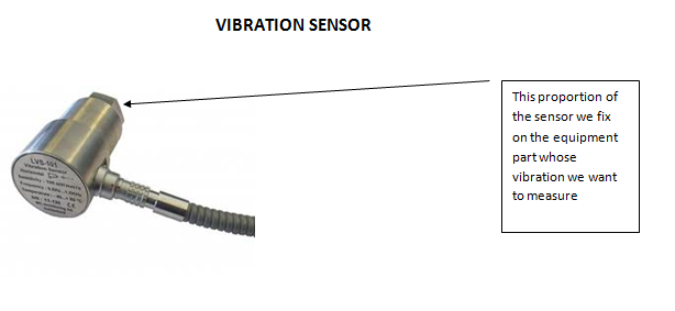
VIBRATION
SENSOR
Vibration
sensor is used to determine the vibration of any equipment. The abnormal
indicative of problems with an industrial machine can be detected and repair
before the event of machine failure because such failure is potentially costly in terms of cost and productivity. The vibration measurement allows the
industrial plant to increase efficiency and save money
Working
The
working of the vibration sensor is based on the LVDT provided inside the sensor
As
there is vibration in the equipment on which it is installed the displacement
occur in the LVDT due to which signal is generated.
The
signal is proportional to the vibration generated. These signal is send to the DCS or to the
interlocking devices.
IN
ACC JAMUL WE MAINTAIN THE VIBRATION UP TO 8mm/sec
VIBRATION
SENSOR
ZSS(Zero speed switch)Zero speed is used to sense to sense the motion of the belt conveyor, bucket elevator .

Output pulse from proximity sensor come to ZSS. If the
pulse from the proximity sensor don’t come it trip the circuit and power will
get cut from the driving motor
There is three setting is given in the zss
SPEED
The speed range is selected according to
the pulse output coming from proximity for each revolution of drive we want to measure .
IBPD
IBPD is define as the initial by pass
delay. The rotating device as initially has zero speed initially so the proximity generates no pulse so the motor get
trip in the starting and motor will not get started so IBPD is given in the ZSS
to give the bypass to ZSS at starting
TRIP
As in the conveyor or bucket elevator a
material get stuck we do not trip the motor immediately so we give the trip
setting to the ZSS for few second so we adjust the trip up to 10 sec to trip
the motor
ReplyDeleteThnq for sharing good article We offer comprehensive range of Syngas analyzer
Portable and Continuous for the analysis of stack/flue gases in exhaust, boiler and combustion process.
Nice blog, thanks for sharing Vibrating Rod Level Switch
ReplyDeleteGreat explanation of RTDs! Could you also explain how RTDs compare to thermocouples in terms of accuracy and cost?
ReplyDeletePallet Rack delhi
Industrial storage rack delhi
I enjoyed reading this! How does the resistance of RTDs change when used in extreme temperatures?
ReplyDeleteIndustrial Pallet Racks india
Mezzanine floor
Interesting post! I’d love to know more about the calibration process of RTDs for industrial applications.
ReplyDeleteSlotted Angle rack
Warehouse storage rack noida
Great content! Are RTDs widely used in the food and beverage industry for precise temperature monitoring?
ReplyDeleteWarehouse Mezzanine Floor noida
Thank you for sharing! What are the typical accuracy levels and response times for RTDs compared to other temperature sensors?
ReplyDeleteHeavy Duty Rack Lucknow
warehouse racking system lucknow
Very informative! Do RTDs require frequent recalibration in industrial settings?
ReplyDeletelong span rack lucknow
Dust collector manufacturer
"Such a valuable and informative post! I truly enjoyed reading it. Thanks a lot for sharing your knowledge with us. Keep up the great work!"
ReplyDeletegondola racks for sale